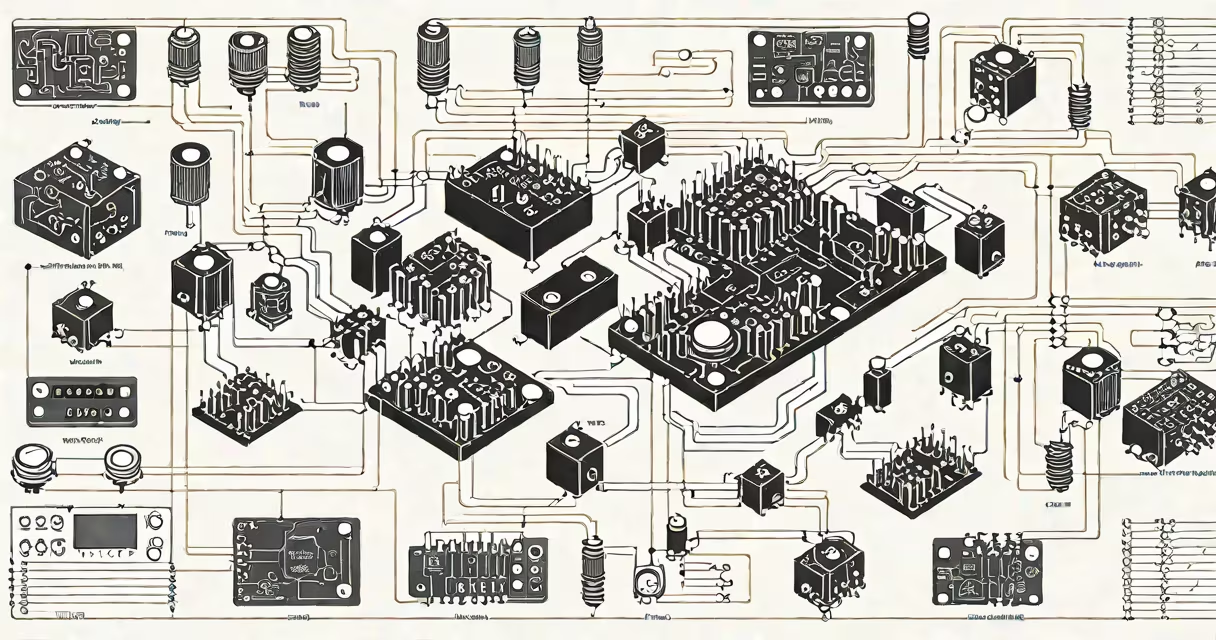
A schematic is a visual representation of an electronic circuit using standardized symbols for components and lines to show electrical connections. It defines how parts interact without showing physical layout. Schematics are essential for designing, troubleshooting, and manufacturing electronics.
Schematics are not blueprints for physical assembly-they don't show wire lengths, component placement, or board size. Instead, they map signal flow and power distribution. A well-made schematic helps every connection is traceable and every function is predictable.
For example, a simple LED blinker circuit uses a 555 timer IC, resistors, capacitors, and an LED. The schematic shows how these parts connect electrically: the capacitor charges through a resistor, triggering the timer's output to switch on and off, cycling current through the LED. This logical structure allows engineers to verify timing, voltage levels, and signal paths before building the actual device.
Schematics rely on a consistent set of symbols recognized globally. Each symbol represents a specific component type: a rectangle with a triangle inside stands for an operational amplifier, while a zigzag line denotes a resistor. These symbols follow standards set by the International Electrotechnical Commission (IEC) and ANSI.
Connections appear where lines intersect. A dot at the intersection indicates a junction; no dot means wires cross without connecting. Lines represent conductive paths. Voltage rails are often shown as horizontal lines labeled "VCC" or "GND," indicating power and ground references.
Consider a microcontroller-based temperature sensor. The schematic includes the microcontroller (e.g., ATmega328P), a thermistor connected via a voltage divider, and a digital output pin tied to an LED. The schematic clarifies that the analog voltage from the thermistor feeds into an ADC pin, which the microcontroller samples every 100 milliseconds. Without this diagram, verifying correct pin assignment or debugging signal noise would take hours.
Creating a schematic begins with selecting software. Popular tools include KiCad (free and open-source), Altium Designer (professional-grade), and EasyEDA (web-based). KiCad supports hierarchical schematics, allowing complex designs to be broken into sub-circuits like power supply, signal processing, and interface modules.
Each component in a schematic must have a footprint-a physical outline for PCB manufacturing. But the schematic itself focuses only on electrical behavior. For example, a 10kΩ resistor appears as a zigzag line with a value label. Its footprint may be a rectangular pad pair, but that detail belongs in the PCB layout phase.
When working with mixed-signal circuits-those combining analog and digital elements-schematics must separate domains. Ground planes should be split or referenced carefully. Using different colors or labels (like "AGND" and "DGND") prevents signal coupling and reduces noise. The IEEE Standard 315-1975 provides symbol guidelines for such cases.
Schematics fall into categories based on complexity and purpose:
| Type | Use Case | Example |
|---|---|---|
| Simple | Basic circuits for learning or prototyping | 555 timer monostable circuit |
| Complex | Microprocessor systems, communication interfaces | ESP32 Wi-Fi module with sensors and battery management |
| Hierarchical | Large systems split into functional blocks | Arduino-based robot with motor control, camera, and wireless comms |
| Power | Regulators, batteries, switching supplies | DC-DC buck converter for 12V to 5V conversion |
One non-obvious rule: avoid crossing wires unless necessary. Overlapping lines can cause confusion. Use "buses"-groups of parallel signals-to reduce clutter. For example, a data bus with eight lines can be drawn as a single thick line with small tick marks and a label like "D[7:0]" instead of eight individual wires.
Another common mistake is omitting reference designators. Every component must have a unique ID like R1, C2, U3. These identifiers link the schematic to the bill of materials (BOM) and PCB layout. Missing or duplicated IDs lead to incorrect parts during assembly.
Schematics are often mistaken for PCB layouts. A PCB layout shows where components sit on a board, how traces run, and how layers stack. The same circuit can have multiple valid layouts depending on space, heat dissipation, or EMI requirements. But the schematic remains unchanged.
For example, a Raspberry Pi Pico project may use a schematic with a microcontroller, USB connector, and pull-up resistors. The PCB layout then determines whether the USB port is placed near the edge or centered, and whether traces are routed under the chip. The schematic doesn't care about position-it only cares that the D+ and D− lines connect correctly.
Also, schematics differ from wiring diagrams. Wiring diagrams show physical wire routing and terminal numbers, often used in automotive or industrial settings. They're less precise for signal analysis and more useful for field technicians replacing cables.
Designing a light-controlled LED system illustrates how to make a schematic step by step.
This schematic is valid for simulation in tools like LTspice. You can test how the LED turns on at 10 lux and off at 100 lux by adjusting the LDR's resistance curve.
I built this circuit on a breadboard during a weekend workshop. The schematic helped me catch a missing pull-down resistor on the transistor base. Without it, the LED flickered randomly. After adding the resistor, the circuit worked reliably.
Always double-check net labels and pin assignments. Mislabeling a power pin can destroy a microcontroller. Use design rule checks (DRC) in your software to flag errors like unconnected pins or duplicate labels.
Refer to official documentation. The IEC 60617 standard defines over 1,000 electrical symbols. The IEEE 315 standard covers logic and control symbols. These ensure consistency across teams and industries.
For beginners, start with free tools like KiCad or EasyEDA. Both offer tutorials and community forums. Once comfortable, explore advanced features like parameter-driven symbols and multi-sheet schematics.
Mastering how to make a schematic enables accurate, reproducible electronic design. It's the foundation of everything from hobby projects to aerospace systems.